Date: 7/14/2024
White Bear Photonics, LLC
2157 Randy Ave
White Bear Lake, MN 55110
Summary
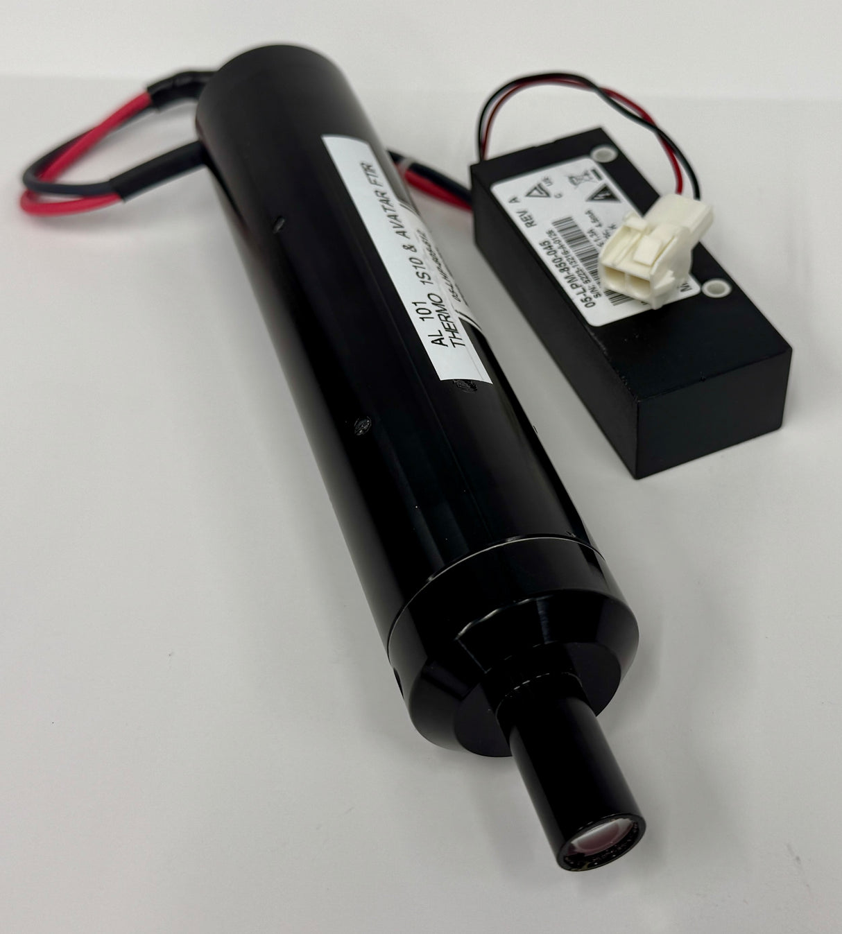
In order, the top three consumables of an FTIR are the desiccant, IR source, and HeNe laser. The HeNe laser is a critical component of the Interferometer and is used to calibrate the instrument as well as control the moving mirror.
Replacement of the HeNe laser is often needed due to:
- High laser gains after alignment (pegged at maximum of 240).
- Scan issues resulting to: no scanning, intermittent bad scans, or noisy data.
- No visible laser light in sample compartment or from the laser head (dead laser).
- Old lasers (from the manufacturing date shown on the head) of more than 7 years will often show one or more of these top three symptoms.
Procedure
Tools needed: Philips screwdriver and SAE hex set for removing and re-installing the laser.
- Turn off the FTIR at the power brick.
- Loosen clamp screws, remove screws to HV brick (under the laser head), unplug connector.

- Be careful removing the laser so it does not touch the printed circuit board. Make sure the brackets are very loose for easy removal of the laser head.
Installation of the new laser
- Install the (copper or black plastic) HV brick. Thread the wires so they do not interfere with the laser head and clamp or cover (near the rubber seal).
- Then carefully rotate the head so the dowel pin is inserted into the collimation lens. Snug the clamps down.
- Power the FTIR up. When the laser turns on make sure the beam is hitting exactly in the center of the beamsplitter. The center of the beamsplitter has a clear aperture for the laser to pass to and from the interferometer. The clear aperture should have the laser centered and be evenly filled so the diodes (detectors) will produce low gain values after the auto alignment. Example of the beam slightly too low shown below.

- If the beam is hitting too low or too high, loosen the laser head clamps the rotate the head so the beam is centered on the clear aperture of the beam splitter, then tighten the clamps down.

- When centered, secure the laser head clamps, and close up the instrument. The issue is there is “slop” in laser head mount in the dowel pin. So this check is important since you can easily install the laser and have the beam misaligned to the extent of the machine not functioning properly (having high laser gains, and bad scans).
- Open the Omnic Application.
- Go into Experiment Setup, then the Diagnostics tab.
- Hit Align and verify the alignment has completed. If this step cannot be completed, then there is either a problem with the beam not centered or some other issue (e.g., bad OBC board).
- When the alignment is complete you should see an interferogram.
- Close out of Omnic and go into the C-drive->programs86->Omnic Folder. Pin the application called ISerDiag to the taskbar (so you do not have to hunt for it next time).
- Open ISerDiag:

- Hit the Laser icon you will see:

- Take a screen shot or record the MCoilX and MCoilY (for future reference). After alignment this is where the reference mirror is parked. High voltages (well above 5) will suggest the interferometer is not calibrated correctly.
- Hit Laser Gains icon:

- Take a screen shot of this and record the date of this laser change. Note all of the gain values should ideally be less than 100 with a new laser. If one of these parameters is 240 the laser will need to be physically re-aligned the so the laser beam is properly hitting all three diodes. In a high laser gain state, the IS10 may still appear to scan, but will be unstable and will intermittently generate bad scans when taking data. If all of the gains are high and between 100-240, this would indicate the KBR beamsplitter in the interferometer is likely damaged from high humidity.


